![biarri-networks-logo.png]](https://fondhelp.biarrinetworks.com/hs-fs/hubfs/biarri-networks-logo.png?height=40&name=biarri-networks-logo.png)
Construction prints turn your design into a set of map sheets for review, permitting and the field. Each set comes as a PDF to view or print and a matching DXF to open in CAD software.
Construction prints are available in Fiber Design and Power Design projects.
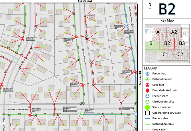
What you get
| Project type | Files | What they show |
|---|---|---|
| Fiber Design | <Version>_Optical.pdf and .dxf |
The fiber network: hubs, splices, cables and premises |
<Version>_Physical.pdf and .dxf |
The physical network: conduit, aerial spans, underground structures and poles | |
| Power Design | <Version>_Electrical.pdf and .dxf |
The electrical network: source hubs, transformers, boxes, meters and wires |
Files are named after the project version they were created from.
How the prints are laid out
Prints are A3 landscape (420 × 297 mm, or approx 11 x 17") at a scale of 1:1000. Each PDF contains, in order:
- Grid Map: an overview of the whole design area, with every sheet outlined and labelled
- Bill of Materials: quantities only, without costs (Fiber Design Optical set only)
- Detailed map sheets, named by row and column: Page A1, Page A2, Page B1 and so on
FOND covers the design area with as few sheets as possible, in horizontal rows. The rows don’t necessarily line up with each other, so use the Grid Map to find the sheet you need.
Each map sheet includes
- The main map, on a map background showing street names and house numbers. Where the map continues onto another sheet, the edge is marked, for example See sheet B2.
- A north arrow and the sheet ID
- A key map showing this sheet and the sheets around it
- A legend
- A scale bar and page number
What’s on each set
Fiber Design: Optical
- Hubs, labelled with their ID, placement (for example, aerial or underground), size and splitter ratio
- Splices, labelled with their ID and placement
- Fiber cables, with each tier drawn side by side so they don’t overlap
- Arrows showing the feed direction where cables arrive at a hub or splice
- Premises, underground structures, poles, parcels and the design area boundary
- Lengths, in your project’s units
The Grid Map shows distribution and drop hubs and cables. The key map also shows feeder cables.
The Bill of Materials pages list quantities only. For costs, use the BOM in the Artifacts step.
Fiber Design: Physical
- Conduit, aerial spans and civil works, with lengths
- Underground structures and poles
- Premises, parcels and the design area boundary
Power Design: Electrical
- Source hubs, transformers (by phase), primary joint boxes and secondary pull boxes, and meters, each labelled with its ID
- Primary wires by phase, with three-phase wire drawn thicker, and secondary wires
- Parcels and the boundary
Electrical prints use a standard power color scheme rather than your project’s map styles.
Create construction prints
- Make sure your design is complete.
- Open the design step:
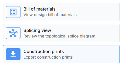
- Fiber Design: Artifacts › Construction prints
- Power Design: Artifacts › Construction prints
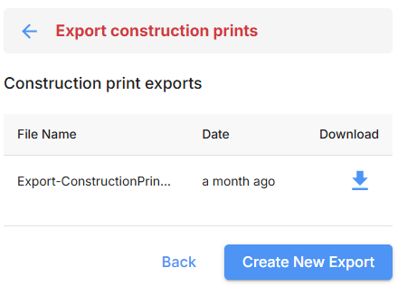
- Click Create New Export.
There are no settings to choose. FOND creates prints for the project version you’re currently viewing. It can take a few minutes, and the progress bar shows activity rather than a percentage.
When the prints are ready, they appear in the list with a Download link. The 15 most recent exports are listed. Click Download to get a ZIP file. Your PDF and DXF files are in its Prints folder.
 |
|
You can also create prints from the main Export window, bundled with your design layers as GeoJSON, Shapefile, KML or TAB files. Tick Construction Prints, along with at least one layer. See Export a project.
Good to know
- Prints are a snapshot. They show your design at the moment you created them. After you update your design, create a new export.
- Prints can’t be customized (yet). Paper size, scale, layers, labels and FOND branding are all fixed, and there’s no title block for a project name, date or revision. If you need these, add them in your CAD software using the DXF.
- To create prints for a different version, switch to that version first. See Project versions.
- If an export fails, it disappears from the list. Click Create New Export to try again. You can see failed exports under Failed Exports in the main Export window.