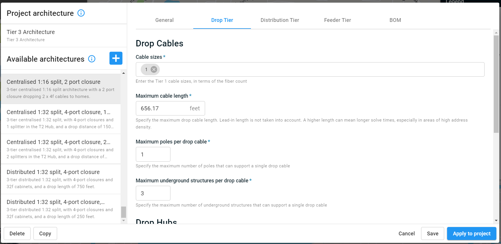
Drop cables
Cable sizes
Enter the sizes of the drops cable to use, in terms of the fiber count. For example, drop cables are very commonly 1f or 2f.
Maximum cable length
Specify the maximum drop cable length.
Please note: Increasing the maximum drop cable length increases the complexity of the problem for algorithms (it has more options), and so will increase the design time. The maximum length is restricted to 2,000 feet. If you feel you need longer cables, reach out to fondhelp@biarrinetworks.com for assistance.
Additionally, FOND will break the maximum only if it absolutely has to. For example, if an address point is 500ft from the nearest segment of the underground path or pole, but the maximum drop cable length is 300ft, FOND will still serve that address by breaking the maximum length rule in that specific case only.
Maximum poles and underground structures per drop cable
Specify the maximum number of poles or underground structures that a drop cable can pass through between the drop hub and a service location. This count does not include the structure of pole at the drop hub location. For example,
| A value of 0 means that each drop is limited to the path between an address and the nearest structure/pole. With this value, a drop will never be placed on an aerial span or in a conduit; it will only follow the "leadin" path to an address. | 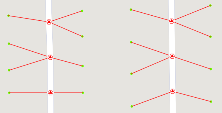 |
| A value of 1 means that each drop can pass through a single structure/pole on its path between the drop hub and an address. As a result, it can only pass through a single aerial span or conduit. | 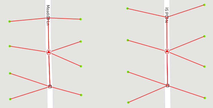 |
| Increasing the value to 4 allows a drop to pass through up to four structures/poles on its path between the drop hub and an address. The maximum cable length and port count must be sufficiently large to allow this to take effect (see the tip below). | 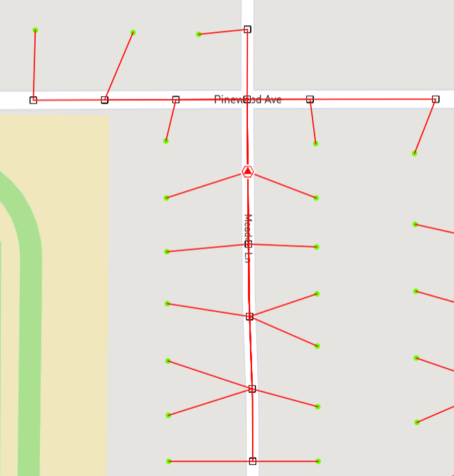 |
Keep in mind that the Maximum cable length, Maximum poles/underground structures per drop cable, and Drop hub port counts can limit each other.
- A drop will never utilize a large number of poles/structures if the maximum cable length is very low;
- A drop will never utilize a large number of poles/structures if the hub port count is low and the addresses dense (cables will simply not need to travel far to reach demand);
- A drop will never utilize reach its maximum length if the maximum poles/structures is too low.
When is this relevant? It's common that drops are not constructed until the time of subscription, in which case you may wish to minimize the scope of drop installation by limiting the number of poles required for attachment, or structures required for access.
Drop hubs
Hub port counts
Setting the Drop Hub port count limits the number of drops that can come out of a drop hub. If your drop hub doesn't have a port limit, set this to be the maximum number of drops that you're willing to splice (or connect) into a single location. FOND will never break this rule (it's a hard constraint). Wherever possible, FOND will serve as many subscribers from the Drop Hub as it can - so long as the maximum Drop Cable length is not exceeded.
Split ratio
Use this to specify whether the drop hubs should contain splitters or not, and at what ratio. You can choose one split ratio, and note that the drop hub port counts must be divisible by this. For example, in order to use a 1:4 splitter you must have drop hubs with at least four ports, and you cannot have a drop hub with 6 ports because it is not divisible by 4.
The split ratio combined with the port counts determines the number of splitters that may be placed inside a drop hub. For example, an 8-port hub could contain up to two 1:4 splitters.
Spare ports
In some cases, you may wish to use a certain closure size, but serve fewer subscribers than the maximum.
Use the Spare ports parameter to specify the absolute number or percentage of ports to be kept spare. For example, 4-port hubs with 1 spare port would never be allowed by FOND to serve more than three service locations, leaving you some space for future subscribers.
If a spare percentage is used, then FOND determines how many ports it is allowed to utilize in each hub according to the formula
capacity = ceiling(hub size * (1 - spare fraction))
Connect spare ports upstream
Toggle this on if you need the spare ports to be fully connected all the way up to the central office. This allows the spare capacity to be considered in the higher tiers of the network, and is particularly relevant if you are intending to make use of the splice tables and avoid re-splicing for future subscribers.