![biarri-networks-logo.png]](https://fondhelp.biarrinetworks.com/hs-fs/hubfs/biarri-networks-logo.png?height=40&name=biarri-networks-logo.png)
This guide takes you through the whole Power Design workflow once: from an empty project to a power distribution design for a subdivision, with transformers, primary and secondary wiring, a bill of materials (BOM) and construction prints.
Each step links to a more detailed article for when you’re ready to go further.
How Power Design differs from Fiber Design
If you’ve used Fiber Design, much of this will feel familiar. You’ll use the same input data layers, data preparation and drawing tools. The main differences are:
| Fiber Design | Power Design | |
|---|---|---|
| Architecture | Fiber tiers, equipment, Demand Model and BOM, shared across your workspace | Electrical rules (meter load, transformers, primary and secondary wire), saved with the project |
| Controlling the design | Blockers, moving hubs, drop assignments, path preferences | Optimize: source hubs, blockers and fixed transformers. Override: footprint, 3-phase path, loop connections and phases. |
| Outputs | BOM, splice records, service areas, construction prints, reports | BOM, construction prints |
How the steps work
The design panel has four steps: Architecture, Input data, Design and Artifacts. Each step opens once every step before it is complete. Artifacts are optional.
Before you start
- Power Design is available by request. Your workspace needs a Power Design subscription, and you need a platform seat. Contact us to set up a trial.
- For your first design, pick a small area, such as a single subdivision.
Step 1: Create a project
On the home page, click Create, choose Multi-Utility Design Project, and give the project a name you’ll recognize later, such as the subdivision name. You may also want to choose a folder.
More information: Create and manage projects
Step 2: Set up the architecture
The architecture sets the electrical rules FOND follows when it designs your network. Click Select architecture and work through the three tabs, using Next to move between them. Then click Save.
| Tab | Settings | Defaults |
|---|---|---|
| Transformers | Average meter load: the load assumed for every address. Transformer sizes: which sizes to use (15, 25, 50 or 75 kVA), and how many addresses each feeds on average. FOND works out each transformer’s maximum secondary load from these. | 60 A per meter. 25 kVA (2 addresses) and 50 kVA (4 addresses). |
| Primary | Primary voltage, Max source load, and the primary wire options the design may use: single-, two- or three-phase | 14,400 V. 140 A. Single- and three-phase. |
| Secondary | Secondary wire options (4/0 for meter connections, and 350, with pull boxes where it breaks out to 4/0), and Maximum secondary wire length between a transformer and a meter | Both wire types on. 200 ft. |
A tab marked with * has a setting that needs attention before you can save.
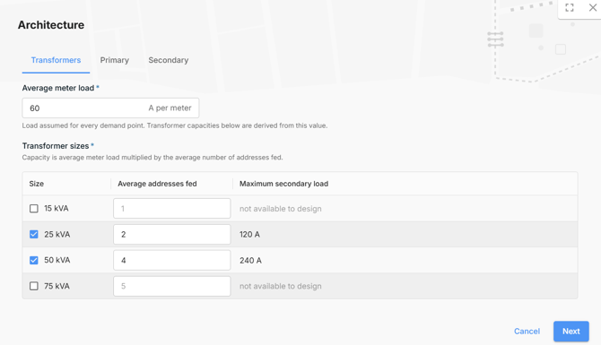
The architecture is saved with the project. Once saved, the panel shows a summary of the key settings.
Step 3: Prepare your input data
Power Design needs addresses, parcels and streets. Poles are optional.
3a. Import addresses, parcels and streets
Use Area Select to import addresses, parcels and streets for your area in one step. FOND’s database covers the USA and Canada. If you have your own data, you can upload it instead.
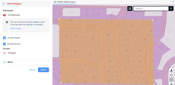
More information: Import data with Area Select · Input data requirements
3b. Add reference data (optional)
Under Reference data, add overlays such as existing utilities, no-build zones, or a scanned site plan. They don’t change your data, but they help you decide what to keep, delete or move in the next steps.
More information: Overlays · Image overlays
3c. Review and clean up your base data
Before you generate anything from your data, check it:
- Addresses: every location you want to serve is there, in the right place.
- Parcels: run Review problematic parcels to remove street parcels and distant parcels, then fix lot lines where needed.
- Streets: every road where you want the network to run has a centerline.
More information: Addresses · Parcels · Review problematic parcels · Streets
3d. Add network sources (optional)
Under Network sources, add the source that will feed your network. You can also do this in the Design step.
More information: Sources (central offices)
3e. Run data preparation
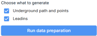
Data preparation generates your candidate network: everywhere FOND could place cable and equipment.
- Under Data preparation, choose what to generate: Underground path and points, Leadins, or both.
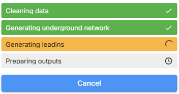
- Click Run data preparation.
FOND uses your parcels, streets and design preferences to generate the underground network and the leadins to each address. If you already have data in those layers, FOND asks before replacing it.
You can also upload or draw the underground network and leadins yourself, and add aerial spans and poles.
3f. Review and refine the candidate network
Review the result before you design:
- Underground path and points: the path follows the right of way, there are enough crossings, and everything is connected.
- Aerial spans and poles (if you’re using aerial): poles are where real poles are, and every span is connected.
- Leadins: every address has one, connected to a sensible point or pole.
Use Refine › Modify data to edit all of these layers together.
More information: Underground path and points · Aerial spans and poles · Leadins · Drawing tools
When all the required layers are complete, you’ll see Your design is ready to be generated. Click Continue.
Step 4: Generate the design
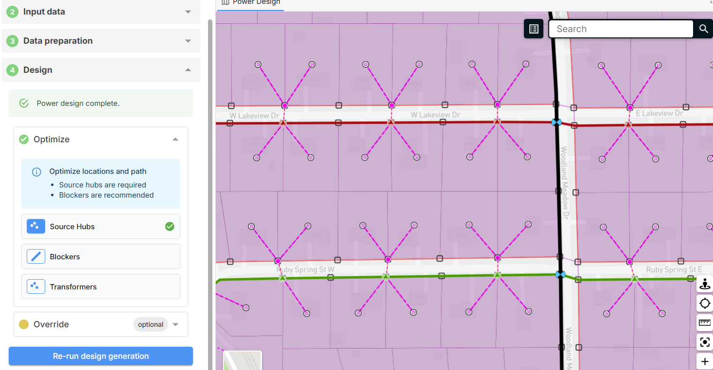
Under Optimize, tell FOND where power comes from and what to avoid:
- Source hubs (required): where power enters the network. Draw or upload them. They snap to underground points and poles.
- Blockers (recommended): lines the design must not cross. You can upload separate primary and secondary blockers.
- Transformers (optional): fix transformer locations you’ve already decided on. Each must sit on an underground point, and not on a source hub.
Then click Start design generation. When it finishes, you’ll see Power design complete, and the map shows your sources, transformers, pull boxes and joint boxes, meters, and primary and secondary wires.
To try different source hubs, blockers or transformers, change them and click Re-run design generation.
Step 5: Override the design (optional)
Once you’re happy with the locations and paths, you can take manual control of the final network.
- Click Lock footprint and transformers. This copies the design’s wiring and transformers into layers you can edit.
- Make your changes:
- Footprint: edit the primary and secondary wire layout.
- 3-phase path: draw the three-phase route from a source hub to a transformer.
- Loop connections: add loops, choosing a wire size and phase.
- Phase overrides: choose a point and change the phase carried by the wires downstream of it.
- Click Re-run design generation.
Overrides lock the Optimize settings. Once you’ve set any override, you can’t change source hubs, blockers or transformers. To change them, click Clear overrides. This permanently deletes all your overrides.
Step 6: Create outputs
In the Artifacts step:
- Bill of materials: review the materials and costs for your design.
- Compare bills of materials: compare BOMs across your project’s versions. This appears when your project has more than one version.
- Construction prints: click Create New Export to produce construction prints.
More information: The interactive BOM · Construction prints
Step 7: Share and export
- Share the project with your team or partners so they can review it on the map and comment.
- Export your design and BOM for your GIS and CAD tools.