Connectorized drop hubs
Use connectorized drop hubs
Toggle on this option if you wish to use drop hubs with connectorized tails.
Daisy chain drop hubs
Toggle on to enable drop hubs to daisy chain to others.
Tail cable sizes
Enter the sizes of the connectorized drops tails to use, in terms of the fiber count.
Here are a few considerations to make:
- Ensure they are large enough for the drop hubs in your design. For example,
- An 8-port drop hub with two 1:4 splitters would require a tail with 2 fibers in order to utilize all drop ports.
- An 8-port drop hub with no splitters would require a tail with 8 fibers in order to utilize all drop ports.
- Ensure they are large enough for the addresses in your design. You should also anticipate the need for larger tails if you have addresses with large fiber counts. For example,
- Consider an architecture that uses 8-port drop hubs with no splitters. If there is an address that requires 12 drop fibers, FOND will attempt to serve this with a dedicated drop hub since a regular 8-port hub is insufficient. This dedicated drop hub will require a tail with 12 fibers. If you don't provide a tail size of 12 (or larger), the design might fail. See Common design failures for more information.
- If you are daisy chaining, ensure the tails are large enough to accommodate multiple drop hubs. For example,
- If each drop hub requires one incoming fibre and you wish to chain up to four hubs at a time, then specify tails with at least 4 fibers. If smaller tails are specified, FOND will always tend to using the smaller cables in favor of chaining the hubs.
Maximum tail length
Specify the maximum length of connectorized tails in your inventory. Later, you can configure the BOM to count the number of tails within specific length intervals.
Number of tails per splice
Specify the maximum number of tails that can be spliced into a single distribution splice closure.
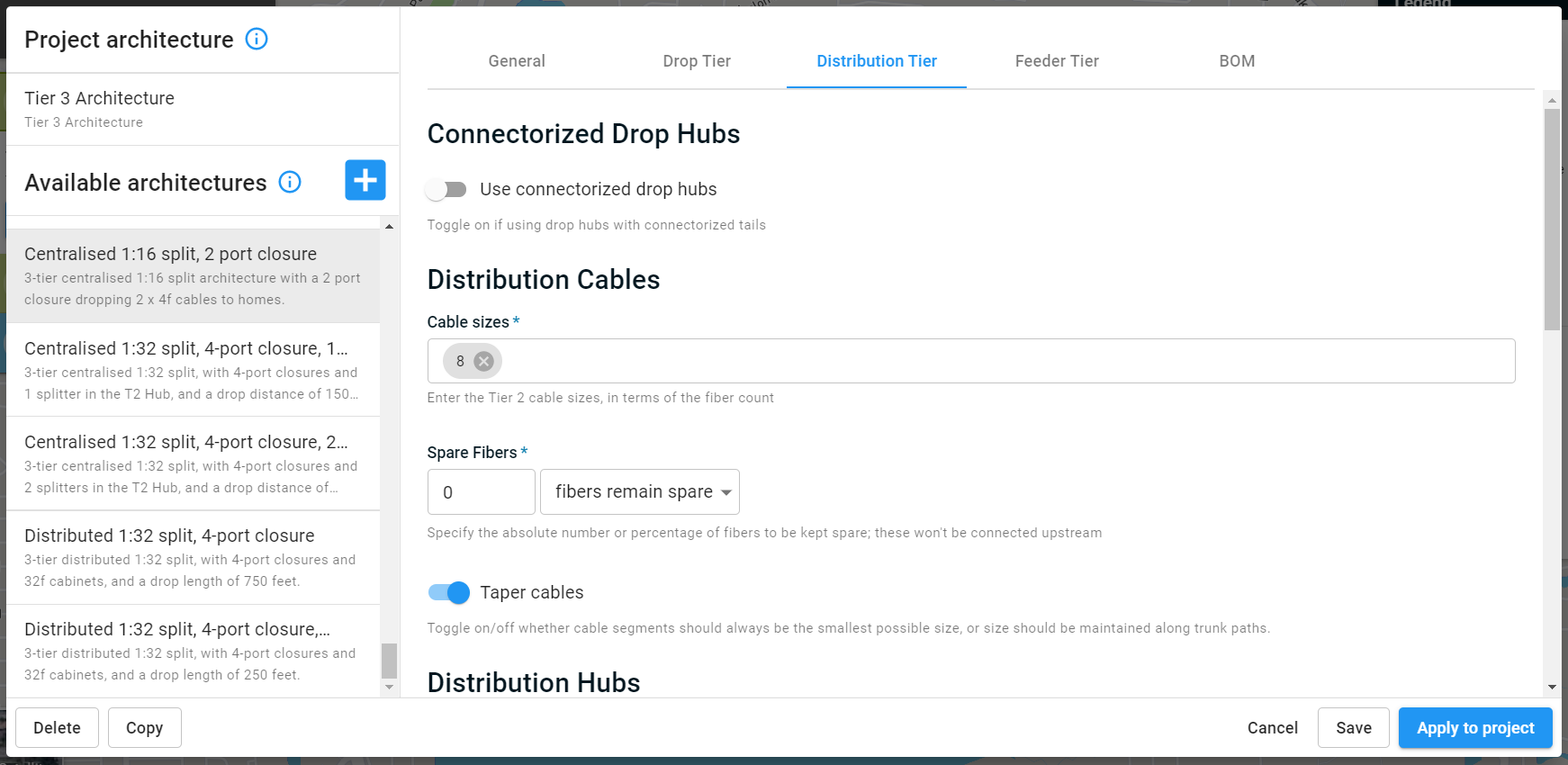
Distribution cables
Cable sizes
Enter the distribution cable sizes, in terms of the fiber count.
Spare Fibers
Specify the absolute number or percentage of fibers to be kept spare. FOND will always use the minimum size cable that's available, so be sure to add some spare as a percent or the absolute number of fibers if you'd like some room for growth in the distribution cables. Note that these spares will not be connected upstream.
Taper cables
When enabled, FOND will determine the amount of fiber required to serve downstream demand, and then always use the minimum cable size that is available from the Cable sizes list.
When disabled, FOND will maintain a trunk of uniformly sized distribution cables along the longest path of the network. Only the size of laterals (branching cables) will be minimized.
Whether you choose to taper cables or not will depend on the relative cost of large cables with ring cuts versus splicing to taper larger cables to smaller ones.
Distribution hubs
Hub port counts
Review and select your distribution hub size(s). The port count is defined as the maximum number of split fibers that may leave the hub in order to serve drop hubs and other demands downstream. For example, a distribution hub with three 1:32 splitters would have a maximum port count of 96.
Split ratio
If you're placing splitters in your cabinet, choose the splitter size that you'll be using.
This is not the overall split ratio, but the actual splitter size in the cabinet. If you're using a distributed (cascaded) split, the split ratio in this step and in the Drop tier will combine to form the overall split ratio. For example, a 1:4 split at the Drop tier and a 1:8 split at the Distribution tier results in an overall 1:32 split at each service location.
Note that if you're trying to configure an architecture for Active Ethernet, that's achieved by setting this parameter to None.
Spare Ports
FOND will always use the smallest distribution hub size available, so you might like to add some spare capacity here as well.
Connect spare ports upstream
This spare can be connected upstream if you wish, by checking 'Connect spare ports upstream'.
Unsplit fiber ports
This represents the maximum number of maximum number of unsplit fibers that may leave the hub in order to serve express demands downstream. See How to control fiber allocation in FOND for instructions on how to allocate unsplit fiber to demands by using the ‘Bypass splitters’ parameter on the address data.
The ports available for unsplit fibers are separate from those defined by the Hub port counts above. That is, utilizing unsplit ports will not reduce the availability of split ports.
Topology
The section on topology allows you to set some parameters that can be used to minimize splice locations in your network. The images below illustrate how setting these parameters can limit the number of splices. It's a good idea to play around with these a bit in some small test areas to see their effect on the design.
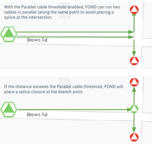
Parallel cable threshold
The parallel cable threshold can be used to enable FOND to run two cables down the same path to avoid placing a splice.
Note: This parameter cannot be used to prevent parallel cables; FOND often needs to run cables in parallel when the downstream demand for fiber exceeds the size of the largest available cable.
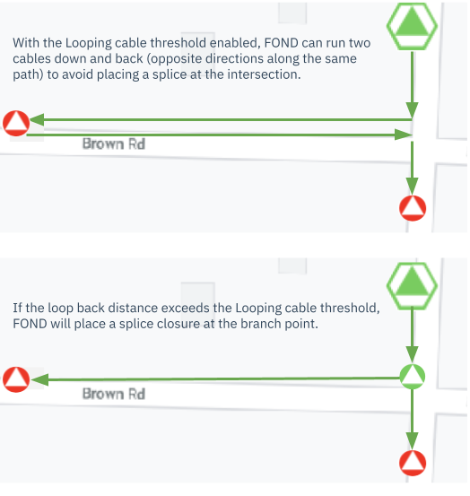
Looping cable threshold
Similarly, the Looping cable threshold can be used to allow FOND to loop the cable back down the same path to avoid placing a splice.
Note that looping may be undesirable if you are maintaining a continuous cable reel with a large bend radius.