As of April 2021, these three example architectures will be available in the architecture panel for all new company accounts. If you joined FOND prior to this date and would like to have them available, talk to the support team so that we may add them to your account.
Generic centralized 1:32
Description: 2-tier centralized 1:32 split, with 8-port drop hubs (2 spare ports connected upstream), cabinets with 3 splitters, and a drop distance of 500 feet

The first defining property of this architecture is that is has two tiers, which is set in the General architecture properties. Centralized architectures can have three tiers as well.
The next defining property of this architecture is that it has a centralized split. In the architecture settings, this is reflected by a split ratio of None at the Drop tier and a split ratio of 1:32 at the Distribution tier. You could use any ratio of your choice, but we've used 1:32 because it is very common. The key to a centralized split is that splitting occurs only at one tier of the network.
In the Drop tier, we have set a single hub port count of 8, and we have specified two spare ports which are connected upstream. This means that FOND will never utilize more than six ports for any drop hub (i.e. drop hubs will serve a maximum of six addresses), and the connectivity of the two spare ports upstream to the distribution hub will be reflected in the splice tables once the design have been generated. The maximum drop cable length is set to 500ft.
Note that with no splitter in the drop hub, the number of fibers spliced into the drop hub from an upstream distribution cable will be equal to the number of drop cables spliced out of the drop hub.
Finally, the description specifies that the cabinet (i.e. the distribution hub) can contain a maximum of three splitters. Three incoming feeder fibers split 32 ways each indicates that we need to set a hub port count of 96. That is, we can have a maximum of 96 distribution fibers out of the distribution hub for service of downstream drop hubs and demands.
Generic distributed 1:32
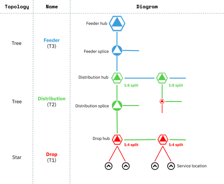
Description: 3-tier distributed 1:32 split, with 4 & 8-port closures, distribution hubs with capacity to split 36 fibers (i.e. 288 out) with 16 fibers reserved for express demand, an OLT capacity of 5,000 addresses, a drop distance of 300 feet, no tapering, looping enabled
The first defining property of this architecture is that is has three tiers, which is set in the General architecture properties.
Next, we know that the architecture has a distributed (cascaded) split with an overall ratio of 1:32. The key to a distributed split is that splitting occurs at multiple tiers in the network. In FOND, we can split at at most two tiers of the network: Drop and Distribution.
Although it's not explicitly stated in the description, we can infer that the split ratio at the Drop tier must be either 1:2 or 1:4 in order to align with our hub port counts of 4 and 8. As per the diagram above, we have chosen to set the Drop split ratio to 1:4 as this is a fairly common setting.
If the drop split ratio is 1:4, then the distribution split ratio must be 1:8 in order to provide us with an overall 1:32 split.
In the Drop tier we have a maximum cable length of 300ft and hub port counts of 4 and 8. Note that a 4-port drop hub will house one 1:4 splitter, and an 8-port drop hub will house two. Consequently, a 4-port drop hub will have one fibre splices into it from an upstream distribution cable, and an 8-port will have two.
In the distribution hub we have the capacity to split 36 incoming feeder fibers; in reality this would depend on the number of available splitter trays and the configuration of splitters within them. At a 1:8 ratio that provides us with up to 288 split distribution fibers (per distribution hub) for downstream drop hubs and demands. In addition to the allocations for split fibers, there is capacity for 16 unsplit fibers for service of express demand (like MDUs or large complexes). These feeder fibers will bypass the 1:8 splitters and will be 1:1 spliced into distribution fibers. In order to utilize unsplit fibers in the design, see How to control fiber allocation in FOND for information about designating Distribution demands which bypass splitters.
The topology of the distribution and feeder tiers is defined by a few parameters. Tapering is disabled, which means that FOND will maintain a trunk cable throughout each tier, spliced down to a smaller cable size only at laterals. By maintaining a trunk, we can maximize the use of cable reels and splice only the fibers that need to branch out into laterals. The parallel and looping threshold parameters have been set at 1500ft and 500ft respectively, in order to further reduce splicing throughout the network.
In the feeder tier, the hub demand count is set to 5,000 to enforce that a single feeder hub (or central office, or OLT) can serve a maximum of 5,000 demands. Remember that this is a theoretical maximum only; see Feeder tier settings for more details.
Generic connectorized
Description: 3-tier centralized 1:32 split, 8-port connectorized drop hubs with max 1500ft tails (4f and 12f)
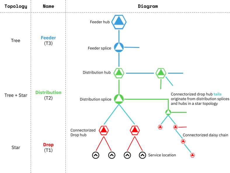
A connectorized architecture implies a slight variation on the network topology as illustrated above. Note that daisy chaining of connectorized hubs is optional, and is not demonstrated in this sample architecture.
As per our first sample architecture, this one is centralized with a 1:32 split at the distribution hub. Connectorized architectures can have distributed splits too.
In the Drop tier, the hub port counts are set to 8 with no spares.
In the Distribution tier, Use connectorized drop hubs is enabled, which reveals several additional settings. First the tail cable sizes are set to 4f and 12f¹, and the maximum tail length is set to 1500ft². These values will be guided by what is available in your inventory, or what specific items you are intending to order from a manufacturer.
¹Note that the tail sizes should be set with the drop hub capacities in mind. For example, with no split at the drop hub, our 4f tails will only ever be utilized when a drop hub serves no more than four addresses. If we hadn't specified 12f cables in our parameters, then we would have no way to serve fully utilized drop hubs and we may encounter a design failure.
²Note that lower maximum tail length values limit the ability for distribution splices to serve clustered drop hubs, which may result in larger quantities of splices (especially in more rural areas).
In this particular architecture we have chosen to set the Number of tails per splice to four. This means that each distribution splice (or hub) can have no more than four tails spliced into it.