![biarri-networks-logo.png]](https://fondhelp.biarrinetworks.com/hs-fs/hubfs/biarri-networks-logo.png?height=40&name=biarri-networks-logo.png)
This guide takes you through the whole Fiber Design workflow once: from an empty project to a fully connected, constructible fiber network with splice records, construction prints, a bill of materials (BOM) and a financial report.
Each step links to a more detailed article for when you’re ready to go further.
How Fiber Design differs from Fiber Planner
If you’ve used Fiber Planner, many of the steps will feel familiar. The main differences are:
| Fiber Planner | Fiber Design | |
|---|---|---|
| Purpose | Feasibility studies and go/no-go decisions | Detailed, constructible network design |
| Input data | Addresses and street centerlines, and optionally aerial spans and poles | Addresses, parcels, streets, a dual- or single-sided underground network, aerial spans and poles, and leadins |
| Controlling the design | Path preferences and moving hubs | Also blockers, drop assignments, side-of-road preferences |
| Outputs | Plan, BOM, Cost to Serve, financial reports | Also splice records, a topological splicing view, service area boundaries and construction prints |
The biggest difference is the input data. A high-fidelity design needs high-fidelity input data, so expect to spend more of your time on the Input Data and Design steps than you would in Fiber Planner. You’re also more likely to go back and forth between the design and refinements, so project versions come in handy for comparing options.
How the steps work
The design panel walks you through five steps: Architecture, Input data, Design, Artifacts and Reports. Each step opens once the step before it is complete. Artifacts and Reports are optional.
Before you start
- You need a FOND account in a workspace with a Fiber Design subscription, and a platform seat assigned to you. See Sign up for FOND.
- For your first design, pick a small area, such as a neighborhood of a few hundred homes. Small areas are quicker to prepare and generate, and easier to review while you learn.
Step 1: Create a project
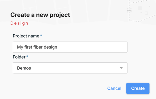
On the home page, click Create, choose Fiber Design project, and give the project a name you’ll recognize later, such as the town or service area. You may also want to choose a folder.
More information: Create and manage projects
Step 2: Choose an architecture
An architecture is the set of rules FOND follows when it designs your network. It covers the number of tiers, the equipment, cable sizes and split ratios for each tier, fiber allocation, and costs.
Click Select architecture, then pick one of your workspace’s architectures and click Apply to project. You can reuse architectures you’ve created for Fiber Planner.
Fiber Design architectures also include design preferences, which shape how FOND builds your candidate network in Step 3:
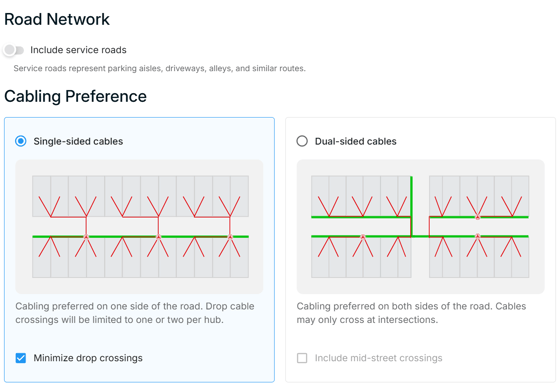
- Road network: whether to Include service roads, such as alleyways and parking aisles
- Cabling preference: Single-sided cables, with an option to minimize drop crossings, or Dual-sided cables, with an option to include mid-street crossings
Check the Demand Model and BOM tabs too. They decide how much fiber each address gets, and what your design will cost.
More information: How to configure an architecture · Fiber allocation and the Demand Model · Configuring your BOM
Step 3: Prepare your input data
This is where much of the work happens. The better your input data, the better your design.
3a. Import addresses, parcels and streets
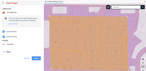
Use Area Select to import addresses, parcels and streets for your area in one step. FOND’s database covers the USA and Canada. If you have your own data, you can upload it instead.
More information: Import data with Area Select · Input data requirements
3b. Add reference data (optional)
Under Reference data, add overlays such as existing utilities, no-build zones, or a scanned site plan. They don’t change your data, but they help you decide what to keep, delete or prefer in the next steps.
More information: Overlays · Image overlays
3c. Review and clean up your base data
Before you generate anything from your data, check it:
- Addresses: every location you want to serve is there, in the right place, with the right AddressType.
- Parcels: run Review problematic parcels to remove street parcels and distant parcels, then fix lot lines where needed.
- Streets: every road where you want the network to run has a centerline.
More information: Addresses · Parcels · Review problematic parcels · Streets
3d. Add network sources (optional)
Under Network sources, add the central office, cabinet or tie-in point that will feed your network. If you leave this empty, FOND chooses for you.
More information: Sources (central offices)
3e. Run data preparation
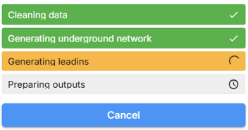
Data preparation generates your candidate network: everywhere FOND could place cable and equipment.
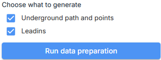
- Under Data preparation, choose what to generate: Underground path and points, Leadins, or both.
- Click Run data preparation.
FOND uses your parcels, streets and design preferences to generate the underground network and the leadins to each address. If you already have data in those layers, FOND asks before replacing it.
You can also upload or draw the underground network and leadins yourself, and add aerial spans and poles.
3f. Review and refine the candidate network
Review the result before you design:
- Underground path and points: the path follows the right of way, there are enough crossings, and everything is connected.
- Aerial spans and poles (if you’re using aerial): poles are where real poles are, and every span is connected.
- Leadins: every address has one, connected to a sensible point or pole.
Use Refine › Modify data to edit all of these layers together, and Path preferences to steer cables onto the side of the road you want.
More information: Underground path and points · Aerial spans and poles · Leadins · Drawing tools · Path preferencing
When all the required layers are complete, you’ll see Your design is ready to be generated. Click Continue.
Step 4: Generate the design
- Choose a Design quality:
- Express: optimized for speed, up to 20 minutes
- Balanced (recommended): balanced quality and time, up to 60 minutes
- Extended: extra time that may give a better design, up to 200 minutes
- Check how many premises generating the design will use from your subscription.
- Click Generate design.
You can leave the project open or come back to it later. When generation finishes, you’ll see Design complete, and the map shows your network.
If the design reports problems, they appear in an Errors list. Click an error for details, and use Open feature inspector to see the affected features on the map.
More information: When is a premises consumed? · Common design failures
Step 5: Review and refine the design
Take time to review what FOND has created. Use the legend to look at one tier at a time, and click hubs and cables to see their details.
If something isn’t right, refine the design:
- Blockers: draw lines that cables must not cross or use.
- Hubs: drag drop and distribution hubs to better locations.
- Drop assignments: reassign service locations to different drop hubs.
Then click Update design to apply your changes.
Tip: Fiber Design work usually goes through several rounds of design and refinement. Before you make big changes, create a new project version with Continue from most recent version. Then you can compare approaches and always get back to an earlier one.
 More information: Inspecting a plan or design · Blockers · Moving hubs · Drop assignments
Step 6: Create outputs
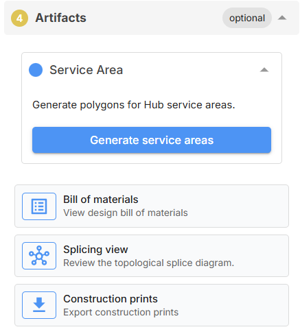
In the Artifacts step, generate the outputs you need:
- Service areas: click Generate service areas to create a boundary polygon for each hub’s service area.
- Bill of materials: explore your design’s materials and costs in the interactive BOM.
- Splicing view: review the splice records in a topological diagram linked to the map.
- Construction prints: click Create New Export to produce optical and physical construction prints in PDF and DXF.
| Service areas | 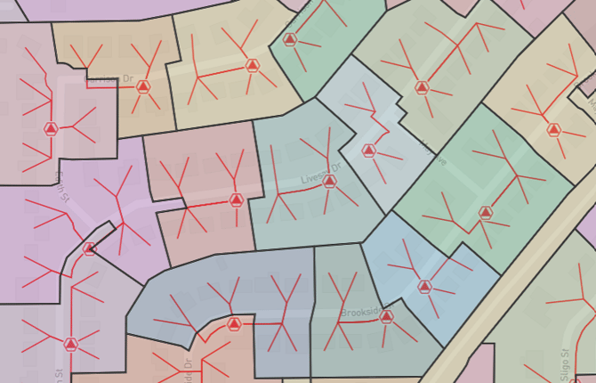 |
| The interactive BOM | 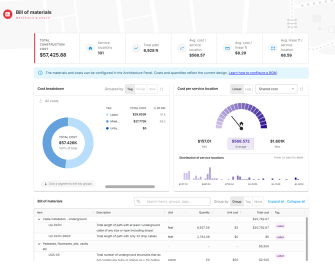 |
| Splicing view | 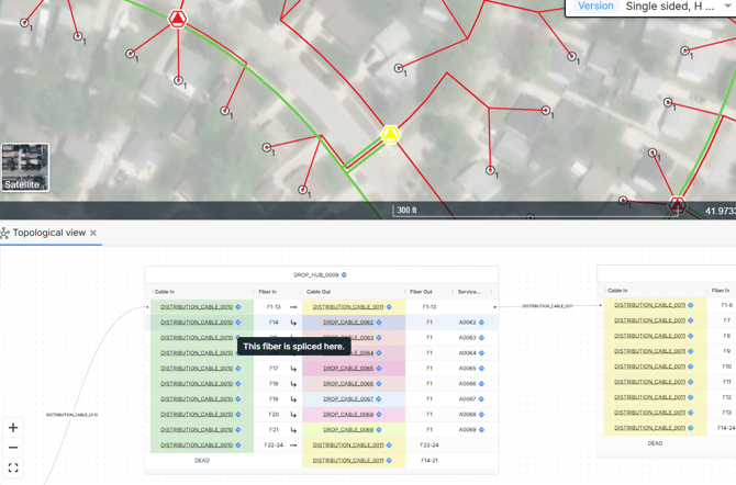 |
| Construction prints | 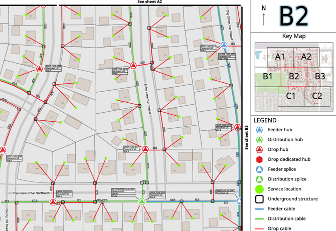 |
Step 7: Create a financial report
A financial report turns your design into a business case, with projected revenue, costs and profitability over time.
In the Reports step, click Configure report. Reports need a complete, up-to-date design, a configured BOM and a completed Demand Model.
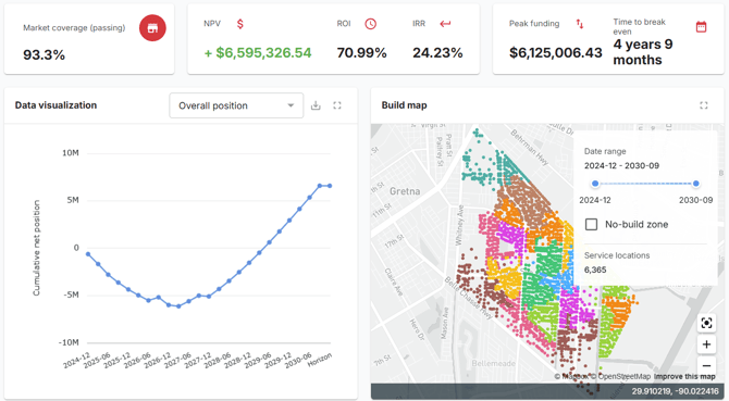
More information: Generating your first report · Minimum report requirements
Step 8: Share and export
- Share the project with your team, delivery partners or customers so they can review it on the map and comment.
- Export your design to Shapefile, GeoJSON, KMZ, CSV, PDF or DXF for your GIS and CAD tools.